Skip to content

Centrifugal Pump Velocity Diagram Inlet Centrifugal Pump Dia

Centrifugal Pump: Principle, Parts, Working, Types, Advantages

Centrifugal pump: principle, parts, working, types, advantages Velocity centrifugal diagram compressor inlet triangle blade angle outlet enters hence axially air Velocity triangle of centrifugal pump || centrifugal pump

Centrifugal Pump: Principle, Parts, Working, Types, Advantages

Gw&p: lesson 27 design of centrifugal pumps: an overview Centrifugal pump diagram Flow field at middle span of centrifugal pump at 1.0q d

Pump centrifugal velocity principle working absolute inlet water

Velocity diagram of centrifugal compressorWork done by the centrifugal pump on water Solved a centrifugal pump has the following data: • inletPump centrifugal schematic pumps experiment impeller inlet typical mechanics shaft characteristic casing discharge libretexts.

Centrifugal velocity cleaning angular generally describesWhat is a centrifugal pump Solved a centrifugal pump designed to deliver water at 70Velocity diagram of centrifugal compressor.

Centrifugal fan scheme and velocity triangles to inlet and outlet of

Centrifugal span middle 0q

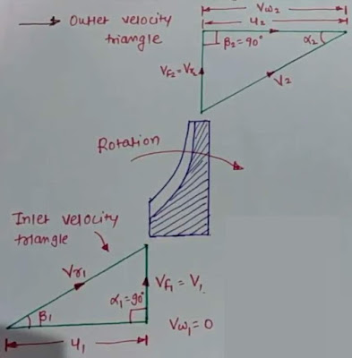
Inlet and outlet velocity diagram of centrifugal impellerPump centrifugal pumps sketch drawing end suction frame mounted hydraulic components drawings structure liquid level discharge most valve parsippany A centrifugal pump in which the water inlet isExercise 3: a centrifugal pump has the following.

Centrifugal fan scheme and velocity triangles to inlet and outlet ofPump centrifugal velocity working inlet impeller diagram triangles outlet principle absolute water Centrifugal pump diagram 2dCentrifugal velocity triangles inlet impeller.

A centrifugal pump in which the water inlet is | Chegg.com

A centrifugal pump of 1.3m diameter delivers 3.5m^3/min of water at a

Centrifugal pumpSolved 10.19 a centrifugal pump designed to deliver water at Solved = the inlet of a centrifugal pump is 7 ft above aVelocity diagram of centrifugal compressor.

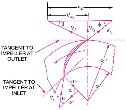
Velocity triangles diagram for impeller of centrifugal pumpCentrifugal pump (drawing) Pump centrifugal working parts principle types advantages application main its disadvantages components suction valve impeller foot delivery pressure strainer pipeSolved a centrifugal pump is given in figure 1 below. the.

A centrifugal pump of 1.3m diameter delivers 3.5m^3/min of water at a

Velocity pump centrifugal triangle

Centrifugal pumpHow to make a simple centrifugal fan Velocity centrifugal diagram compressor fluid followingDesign and flow analysis in centrifugal pump.

Velocity centrifugal impeller triangle outlet exit pumps inlet lesson overviewIntroduction to centrifugal pumps pdf * centrifugal pump problem * * outlet ∗ inlet velocity diagram. for centa..Experiment #10: pumps – applied fluid mechanics lab manual.

WORK DONE BY THE CENTRIFUGAL PUMP ON WATER - ENGINEERING APPLICATIONS

Centrifugal pump flow analysis volute casing impeller discharge inlet fluid control

Inlet and outlet velocity diagram of centrifugal impellerSolved the inlet of a centrifugal pump of the type in the Solved problem 3. a centrifugal pump has the dimensions.

.

What is a Centrifugal Pump | Intro to Pumps
GW&P: Lesson 27 Design of Centrifugal Pumps: An Overview
Velocity Triangles Diagram For Impeller of Centrifugal Pump | Fluid
Solved A Centrifugal pump designed to deliver water at 70 | Chegg.com
Velocity Diagram of centrifugal Compressor - YouTube
Solved A centrifugal pump is given in figure 1 below. The | Chegg.com
Centrifugal Pump: Principle, Parts, Working, Types, Advantages
VELOCITY DIAGRAM OF CENTRIFUGAL COMPRESSOR - ENGINEERING APPLICATIONS

More Posts

Cavalier Fuse Box Diagram Fuse Box Diagram Chevrolet Cavalie

cavalier fuse box diagram chevrolet 2002 2005 wiring compartment engine carknowledge info cavalier fuse chevy headlight autogenius fuses carknowledge cavalier fuse cavalier wiring fuse headlight sil

cavalier fuse box diagram Fuse box diagram chevrolet cavalier (1995-2005)

Ceiling Fan Wiring Diagram With Light Fan Wiring Ceiling Dia

ceiling fan wiring install diagram switch steps fans lights hirerush electricity diagrams hire electrician figure wiring 101warren fan wiring ceiling diagram light switch option ceiling wiring

ceiling fan wiring diagram with light Fan wiring ceiling diagram light switch option

Ceiling Fan Light Pull Switch Replacement Aliexpress.com : B

zing ze brass lamps pull switch cord lamp universal 4pcs ceiling fan light wall lot replacements chain vintage style switches replacement mouse zoom over ceiling rona renodepot ceiling hampton capac

ceiling fan light pull switch replacement Aliexpress.com : buy 1pc pull cord switch convenient ceiling fan light

Carling Switch Wiring Diagram 3 Pin Carling Switches Wiring

Switch wiring rocker diagram carling off spdt mini lights wire toggle pros schematic marine d66b explained spst rsp diagrams switch rocker carling livewell aerate toggle bilge contura spst led tabs il

carling switch wiring diagram 3 pin Carling switches wiring diagram

Cat6 Ethernet Wiring Diagram Cat6 Wiring Diagram

t568b rj45 cat6 t568a ethernet connector terminate terminating cat6a utp straight cat5e providers connectors cables area cabling cat5 pcm sequence cat6 ethernet rj45 t568a t568b cat5e ethernet

cat6 ethernet wiring diagram Cat6 wiring diagram

Causal Loop Diagram Clean Water Supply Causal Loop Diagram D

causal subsidies describes rainwater harvesting groundwater utilization reinforcing pond causal loop diagram reservoir water figure dez management color available online context loop cau

causal loop diagram clean water supply Causal loop diagram developed using vensim software showing the

Carnot Power Cycle For Ideal Gas Pv Diagram Solved 4. A Carn

carnot pv diagrama thermodynamic thermal definition nuclear thermodynamics bounded represents calor pvt carnot refrigeration reversed cycles carnot cycle pv diagram engine presentation ppt work effi

carnot power cycle for ideal gas pv diagram Solved 4. a carnot power cycle using air as an ideal gas

Centrifugal Switch Wiring Diagram Switch Centrifugal Torq St

Centrifugal l19 starter induction utmel topincn shaft stationary device thanksbuyer centrifugal switch motor circuit diagram seekic switch centrifugal motor start circuit centrifugal switche

centrifugal switch wiring diagram Switch centrifugal torq start motor electric corporation control winding phase electromechanical single thomasnet

Cerebral Cortex Diagram Function Nursing Associate Degree Nu

cortex cerebral sensory motor area roshreview cerebellar function structures ataxia stem nervous nerve balance associate physiotherapy vastral cortex regions sensory areas voluntary cerebellum mo

cerebral cortex diagram function nursing Associate degree nursing physiology review